The Development of ANITA
The world's first electronic desktop calculator
Part 2:
John Lloyd joined Bell Punch in 1957 as an electronics engineer to work on the design of electronics calculators. He was involved in the design of all the models of calculator made by the company and became the chief engineer of Sumlock Anita Electronics, when it was formed. He explains:
"In the 1950s the Bell Punch Company held a dominant position in Britain as the manufacturer of mechanical calculators for commercial use. It felt its position threatened by the newly invented electronic computer and brought in Norman Kitz [a.k.a. Norbert Kitz] to explore the possibility of applying electronics to its products."
He started exploring ideas for a machine made of a hybrid of mechanics and electronics. In November 1957 he recruited myself and Hugh Mansford, and the three of us began to consider an entirely electronic machine, with the only moving parts being the keyboard.
In January 1958 we started on the design and by December we had built a working calculator. It occupied about 1 foot square of desk space and calculated the four rules of arithmetic to 10 decimal digits. It used decimal logic and looked similar to the Anitas which were produced later.
The counting was done on Dekatron gas tubes produced by Ericcson Telephones at Beeston, Nottingham. They were driven by hard valve triodes from logic made of solid state diodes configured as AND and OR gates. The components were mounted on printed circuit boards, there was very little wiring.
This machine was subsequently given to the Science Museum at South Kensington, London. The success of this machine allowed the company to fund full scale commercial development and we designed a production prototype.
However a serious snag began to appear. When a Dekatron waited in one position for many hours sputtering of metal from the lit cathode occurred, which caused a change in the electrical characteristics and led to miscounting. A desperate search for a solution proved fruitless and the use of Dekatrons as the counting element was abandoned, being replaced by a ring of 10 gas filled triodes, called trigger tubes, mounted on a printed circuit with the decimal display tube. If cycled continuously the Dekatron performed satisfactorily so was retained as the master oscillator because of its compact size in a machine where space was at a premium. This arrangement was used for all subsequent Anitas up to the Mk 12.
This caused considerable delay and a working prototype of the Anita Mk 7 was not produced until 1960. It was called the Mk 7 because previous production mechanical Sumlocks had developed up to the Mk6, with "SAM" or Semi-Automatic Multiplier, which was considered the acme of electro-mechanical progress.
The Mk 7, however, did not find favour with the company's sales force who were afraid that the new operator skills required would cause confusion among the army of Sumlock operators in the field. The export division welcomed it into their market for decimal calculators and a factory was set up in Portsmouth to produce it. From 1960 many hundreds were exported to continental Europe, mainly Germany, the Netherlands, and Belgium.

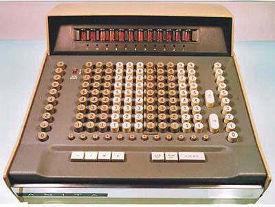
ANITA Mk VII
Development continued to produce a machine to a home market specification, and in September 1961 the Mk 8 was launched. This was also very successful and many thousands were produced at Portsmouth.

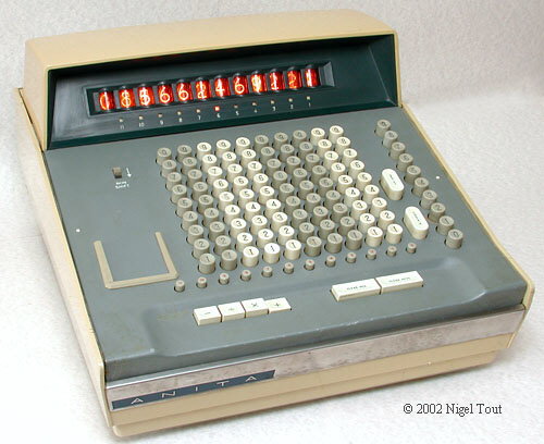
ANITA Mk 8
From then on there was period of steady development of additional features. Decimal points appeared in the Mk 9 and Sterling arithmetic in the Mk 10. Machines which did not go into production included one with the square root function and another with memory.
The last of the series were the Mk 11 and Mk 12 which had the reduced, 10-key, keyboard."
John Smith
was an apprentice who worked in the Sumlock Electronic Development Department. His recollections give a fascinating insight into the early days of the development of the Anita:
"It was during 1956/7 when I started
there. Mr. Kitz was the top dog of the new electronics department when I started. At the beginning there was only Mr Kitz, the man I remember as Les, maybe two others and me. Les I am sure of, I think it was him,
that taught me how to build a diode pump integrator or staircase generator, which I later used to make a transistor tester. Ken may have been one of the others.
The Electronic Development building had been used as an air-raid shelter during the war, but by the time I worked there it had been fitted with windows and been turned into a nice little workshop. It had walls of white brick like the shelter that was in my road for many of my childhood years. I remember being somewhat proud of working there. No other apprentice did. My family boasted to anyone who would listen. Those that did not already knew where my interests lay.
I don't know now the exact order of events but am sure that there were two so called electronics departments. One doing the Sumlock work and one doing the totalisator work. I worked in both at different times but have a clear memory of being in the totalisator section playing with a prototype electronic Sumlock. Can't think why. Have no memory of the other one being closed but it may have been. The totalisator workshop was bigger and ANITA only took up a small area in it.
They had been making mechanical calculators for some time and must have had various material suppliers dependent on them for much of their business. There was probably reluctance to let down all these people. So when they needed groups of ten pulses to start the calculations they tried to generate them using mechanical means. The tests I describe below were done on a mechanical calculator unit's base plate.
Using the motors that were used in the Sumlock mechanical calculators, we drove an arrangement of "brushes" over the surface of a disk that had several groups of 10 contacts embedded in them. They tried many different materials for the disks, contacts and brushes, but failed to find a combination that produced reliable "noise" free useful life time. Either the plastic or the metal contacts got worn and the "brushes" would bounce at the join and produce spurious pulses. The pulses were to be used by the electronics to do the calculations. With my more sophisticated knowledge now I can think of ways round these problems.
They also must have had a mind for an overseas market in countries with humid atmospheres. A lot of experimenting was done on a condition I had not heard of before that time in my life. Apparently metal atoms can migrate through some insulating materials in conditions of an electrical potential gradient and high humidity. They had a tank in which disks of various insulating materials, (I don't suppose the range of plastics was as great as it is now) were suspended. The embedded conductors strapped together in pairs that were connected to a voltage supply. A heated water tray made the inside of the tank very moist. Being the underling it was my job to keep the water topped up and monitor the system for signs that it was passing current where it should not. It was all a waste of time and money because the mechanical means of generating the decimal pulse groups was eventually dumped.
A relay calculator was not attempted [the first Casio calculators built in the mid-1950s used relays] even though relays were very much part of the Totalisators for race courses that they used to make."
After the problems in producing a reliable calculator using electronics driven by mechanically derived pulses, development turned to a purely electronic calculator, with the only moving parts being the keys. This was based on vacuum tubes [thermionic valves], cold cathode trigger tubes, and "Dekatron" counter tubes.
John Smith continues: "I wish I could remember more details, but little bits do come back, like the zero of each counting ring being connected to the driver of the next digit to step it on. The words shift-and-add or shift-and-subtract were part of the maths algorithm. The number keys on the device locked down until the calculation they caused was complete. In one of the early models they did not have the release solenoid mechanism fitted and you had to trip the key release manually. I remember there was an elaborate ritual needed in the order that operator keys and number keys were used to get it to divide. The release was a step most forgot. I got quite good at using it, but it soon went the way of all the others and I had to take it apart for the parts for a later version. I remember the loss I felt.
Some of the "Dekatrons" had 12 cathodes not 10, and were type GS 12D [these were used for setting the decimal point indicator in early prototypes with 12 decades of keys]. Most people won't understand that the "cold cathode" was hotter than the thermionic cathode anyway. I thought of them as trigger tubes, really they were small thyratrons.

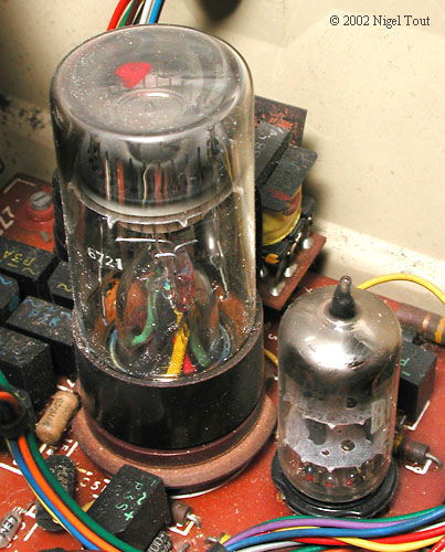
The GS10D "Dekatron" decade counter tube, with the small vacuum tube (thermionic valve) to its right, which is part of a blocking oscillator circuit providing driving pulses at a rate of 4000 per second in an ANITA Mk 8 calculator.
Siemens "Dekatron" tubes were tried and rejected. As for why they were no good, two words, learned then and not forgotten: sputtering and poisoning:
- Sputtering: The bombardment of the cathode by fast heavy positive gas ions that smash metal atoms from its surface and spreads them over everything around them. This causes insulators to get conducting coats of metal and glass to silver over until you can't see the glow. Neither a good outcome.
- Poisoning: An effect that takes place on the surface of metal that is sputtered which makes it less conductive. Sort of survival of the fittest effect. If you don't give off electrons you don't get smashed by electron hungry ions. Net result, the striking voltage gradually goes up until it doesn't strike at all. OOps gives wrong answer.
The trigger tubes also suffered from sputtering and poisoning, but having much less crowded electrodes and no need for the glass to be transparent they lasted much longer.
[There were problems with the early, Mk 7 ANITA calculators which had two Dekatrons, one of which remained idle for long periods and was prone to problems due to sputtering.] They did build a model with a circuit that drove the glow round the ring continuously when the thing was idle. Supposed to stop the zero cathode (the usual one it was idle on) from being poisoned. It did lengthen the tube life but, the circuit got too complex for the box and was abandoned. That was when they started using trigger tube rings and "NIXIE" indicators. [Apparently, before the use of "Nixie" numerical display tubes, Dekatron counter tubes behind numbered plastic had been used for the numerical display.]
Since I have been prodding this area of my life I have a clear memory of a loud crack and tinkle as a transistor exploded in one of the breadboards as someone switched it back on after a wiring modification had connected a lead to the wrong tag. Must have been a gas tube/transistor hybrid with high and low voltages.
Before my time in that department had ended I saw the first PCB going over a wave soldering machine. (I was there when the machine was delivered.) I was amazed any of the components survived. The flux pre-coating gave off clouds of smoke and there were no hoods and extractor fans in the place. I suppose they were too eager to try the new toy or did not realise it did that.
I was moved into the electro-mechanical tote [totalisator] section after that time and was being stuffed with a host of new concepts. It's sad that I did not realise what an historic event I was involved in or I might have made some sort of record."
Copyright © 2001 John Lloyd and John Smith.
Unsuccessful attempts were also made to use "Trochatron" counter tubes instead of the Dekatron tubes. These are similar to the Dekatrons but the electrodes are mounted within a magnetic field
It is possible to view United States Patent 3,280,315 (filed Dec. 29, 1961, granted Oct. 18, 1966) which describes in great detail the operation of both the unsuccessful mechanical-electronic version of the ANITA and the successful purely electronic version.
A technical article by Norbert Kitz for a symposium at Cambridge University in March 1964 gives some technical details of the circuits, and notes that they were based on decimal arithmetic not binary - as he said "… no binary stunts here !"[1]
Reference:
The Bell Punch Company & the Development of the Anita Calculator
< Previous page Next page >
Text & photographs copyright © 2002 - 2023 Nigel Tout, except where noted otherwise.